How it works
Assembly Instructions
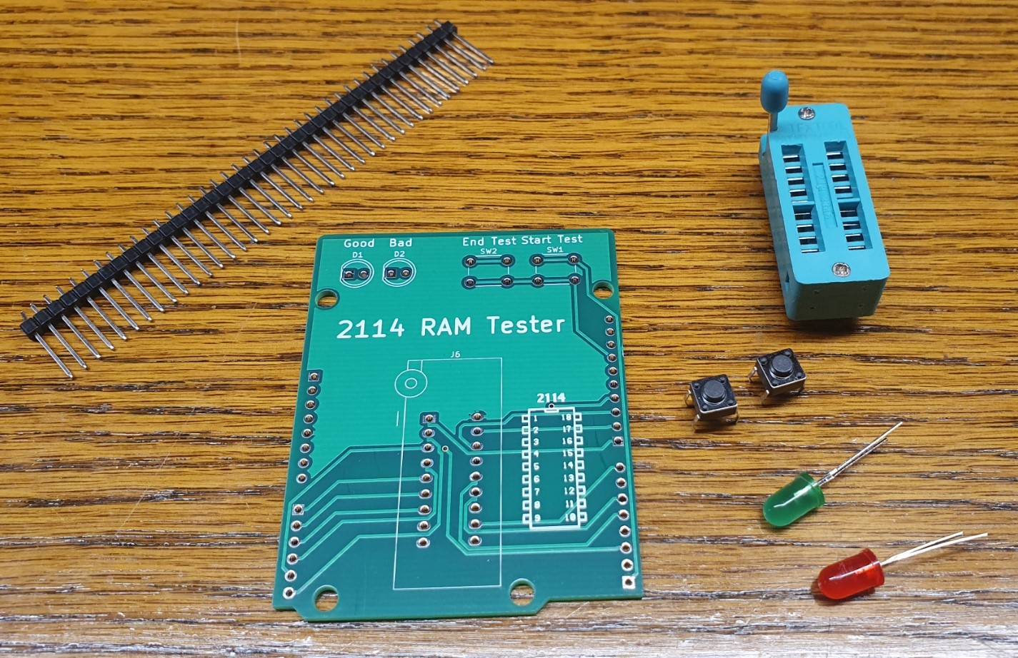
1. Parts included - These are the parts that are included in the kit. You will also need a soldering iron, an Arduino Uno, wire cutters, and a PC with a USB port.
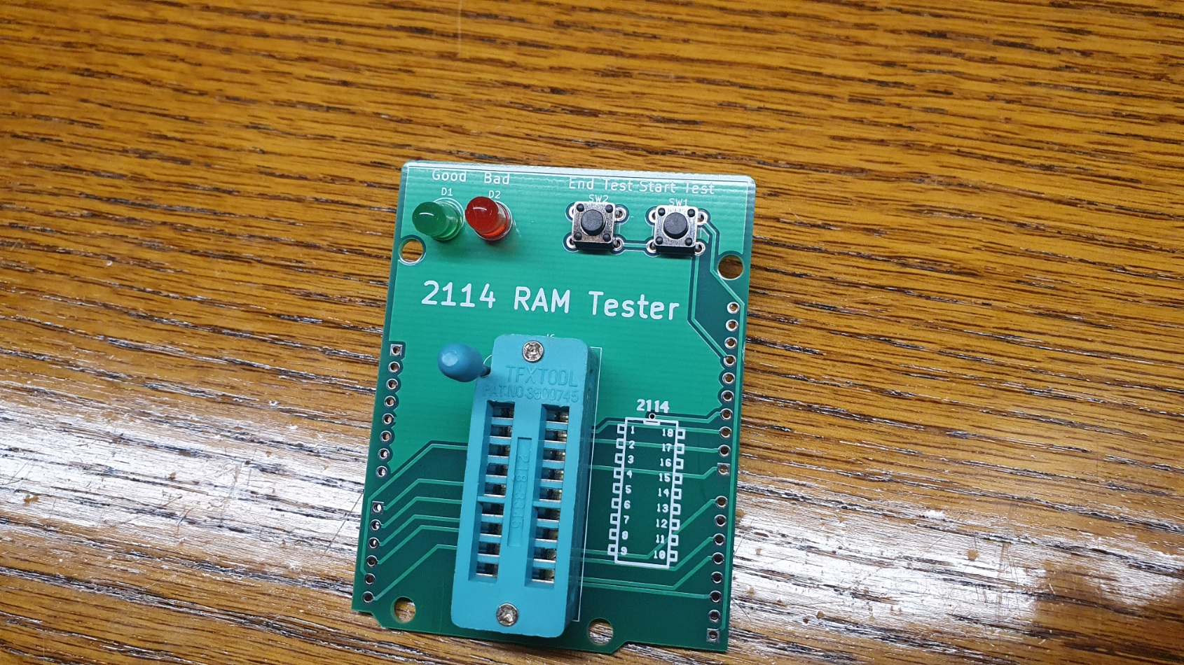
2. Assemble upper components. Insert LEDs, Switches, and the zif socket. LEDs must be inserted in the correct orientation. The longer leg should be inserted in the hole on the opposite side of the flat mark on the board.

3. The board should look like this with the components inserted.
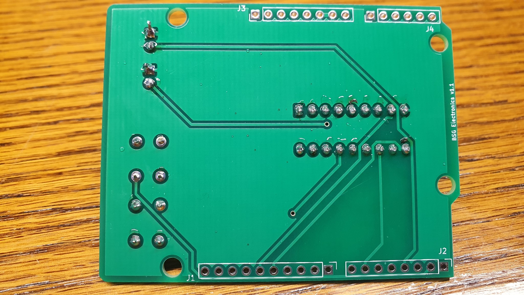
4. Flip the board over and solder in the components. Ensure that extra solder does not connect any pins. Trim the extra wire length off the led legs.
5. Now cut the pins to fit into the series of holes on the edges of the board. Extra pins can be saved or discarded.
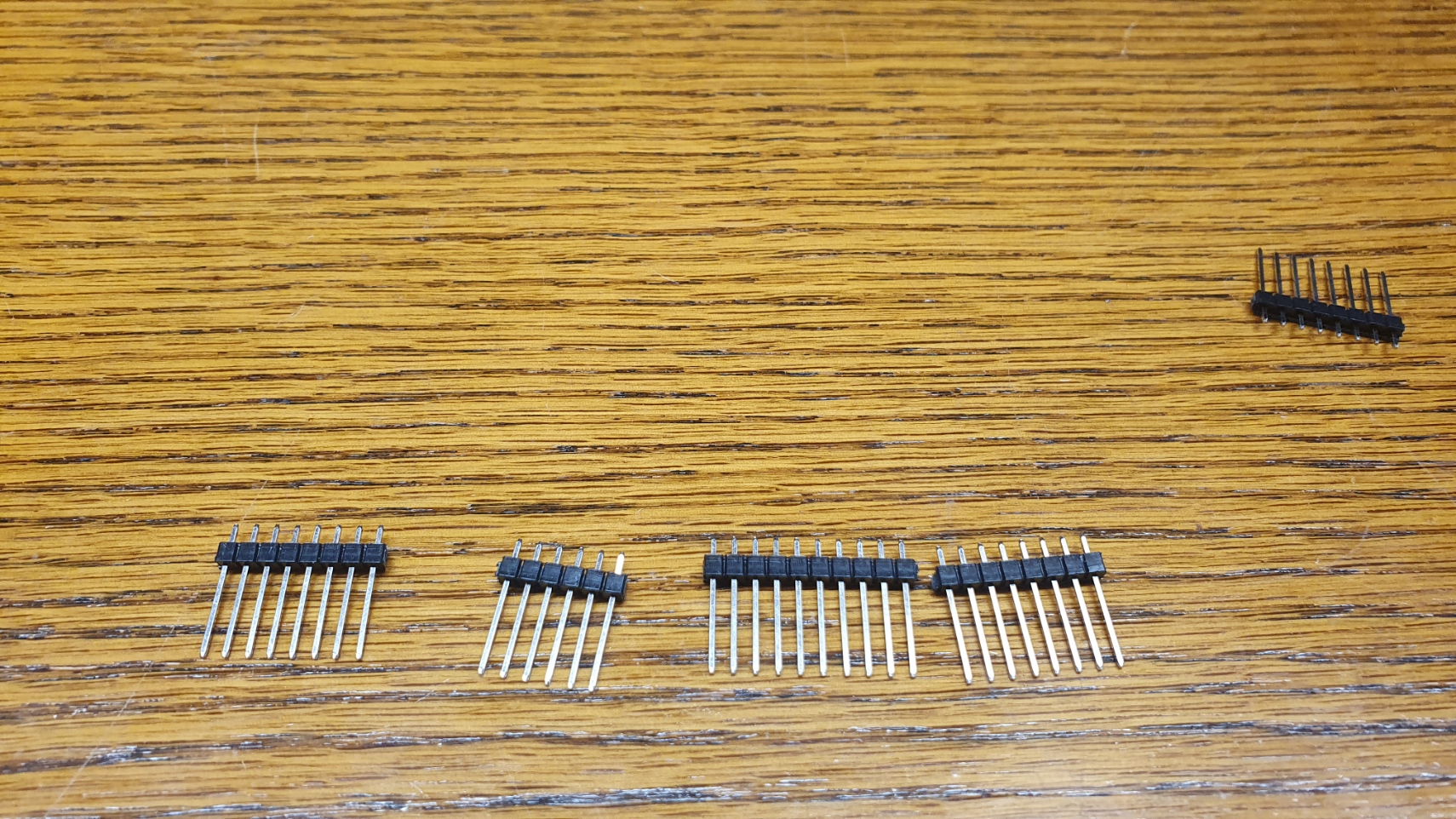
6. Insert the pin sets as shown.
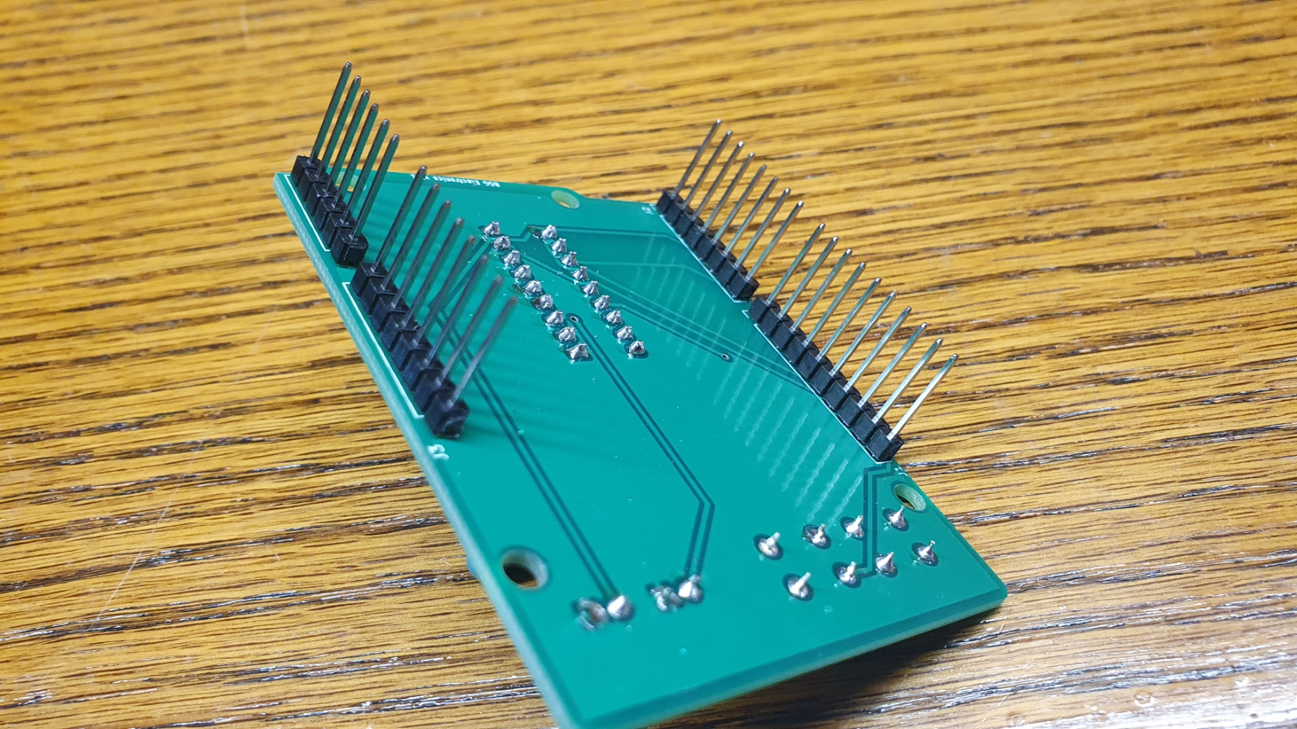
7. Solder pins from the top of the board and install the completed shield on your Arduino Uno

8. Download and install the Arduino IDE software from arduino.cc
https://www.arduino.cc/en/software
9. Download the 2114 memory test source code. Select "Code" > "Download Zip". Extract zip file and save Test2114.ino
https://github.com/cpyne/2114MemTest
10. Connect your Arduino Uno to your computer via USB.
11. Launch the Arduino IDE software. Make sure "Arduino Uno" and your appropriate COM port are both selected under the Tools menu.
12. Select File > Open and then select the Test2114.ino file that you downloaded in step 10
13. Select "Sketch" > "Upload" to load the file to your Arduino. *Note - If you encounter an upload error, retry with the shield disconnected from your Arduino.
Using the 2114 Tester
1. Plug the Arduino in with a 9v power supply or USB.
2. Insert the 2114 chip to be tested. Semi circle mark should be pointing towards the leds. (pin 1 in the upper left)
2. Press Begin Test to run test cycle.
3. Press and hold End Test to stop
4. Green = Good, Red = Bad
5. Testing will run in a loop and red will turn on, and remain on, if an error is encountered. This can be used for longer testing to rule out intermitted failures.

Comments (2)
I Have just received the 2114 RAM tester kit. Instructions are Great. Waiting for the Arduino. Do you have anything to test LH5101 static RAM chips (separate I/O).
Thank you for the order. Sorry, nothing for LH5101 chips at this time.